Boat Leveler Wiring Diagram

Typical Wiring Schematic Diagram Boat Wiring Electric Boat

Need Wiring Diagram For A Boat Leveler Trim Tabs

Boat Amplifier Wiring Diagram Boat Wiring Electrical Wiring

Boat Wiring Diagram With Images Boat Wiring Boat Restoration

Boat Wiring Diagram Google Search With Images Boat Wiring

Owners Manual Insta Trim Boat Levelers

I had a project in mind but decided against using them.
Boat leveler wiring diagram. Insta trim boat leveler tabs are two stainless steel planes installed on the transom. Here are the colors for boat leveler. How insta trim boat levelers work. Wire colors and their functions.
This waterflow creates upward pressure under the trim tabs raising the stern. Quick review of the box contents of the insta trim boat leveler pump. This allows you to open the switch turning everything off at once. Product was packaged great included all the correct hardware and an instruction page harness consists of two 14 gauge leads.
Instatrim with 12 tabs. Insta trim trim tabs are designed to adjust for these changing conditions and provide lift in order to give you the best possible running attitude for your motor boat. Many have an inline fuse on this wire which should be 20 amp fuse. The motor used in all insta trim systems is a powerhouse with coated wiring and a built in thermo overload which protects against temperature and amperage build up.
It reveals the components of the circuit as streamlined forms and the power and signal links in between the tools. A wiring diagram is a streamlined conventional photographic representation of an electric circuit. The motor is made up of 1 3 4 stack windings and is mounted on top of the hydraulic pump eliminating oil leakage. As the hydraulic cylinders deflect the trim tabs water flow is redirected.
In nearly all cases your boat wiring system should have a marine grade main battery disconnect switch. Assortment of boat dock wiring diagram. A trim tab set up i bought. Some merchandise may be limited in supply or available only by special order.
12 x 11 heavy duty dual cylinder trim tab set. As the stern rises the bow lowers figure 1. Just set them up to demonstrate them. In this case we ve shown an 1 2 both type battery switch.
Red hot is for 12 volt power supply which have fuse protection.

Simple To Read Wiring Diagram For A Boat Boat Wiring Electrical

Click Image For Larger Version Name Gw Wiring Diagrams 1 Jpg

25 Good Wiring Diagram Software Technique With Images Boat

Wiring Boat Navigation Lights 24v Boat Wiring Diagram 24v
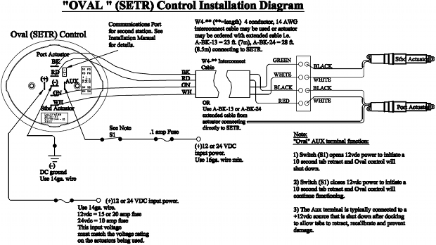
Wiring Diagram Oval Led Control Setr Series Lectrotab

Diagrams Digramssample Diagramimages Wiringdiagramsample
Old Mercs Wiring 1966 On With Images Mercury Outboard Boat
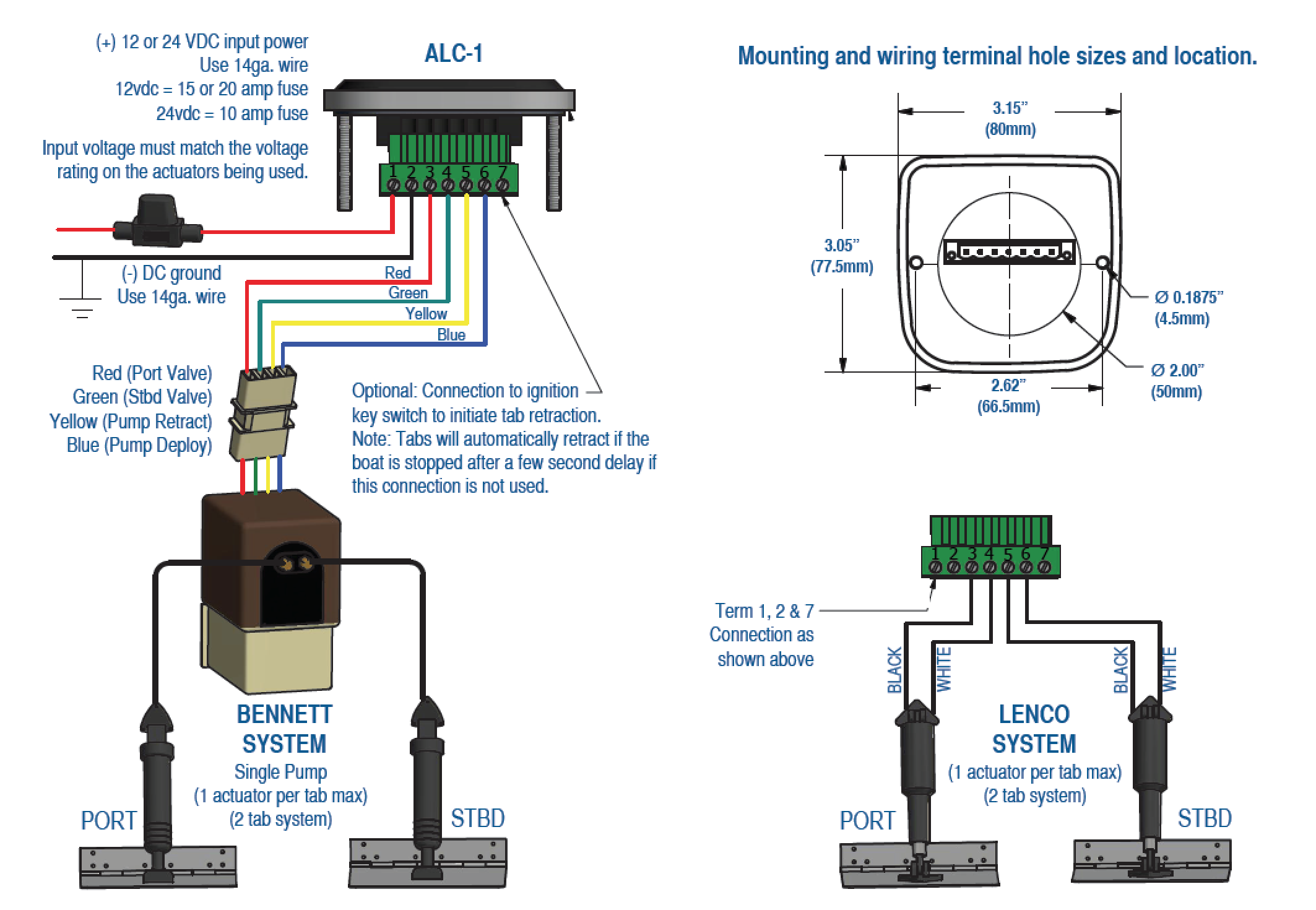
Automatic Level Control For Lenco And Bennett Products

Newbie Switch Panel Wiring Questions The Hull Truth Boating

Boat Wiring Diagram With Images Boat Wiring

Marine Navigation Lights Wiring Diagram

Generic Boat Wiring Diagram By Silvertip Page 1 Iboats Boating

Wg 7074 Mercruiser Trim Wiring Diagram As Well As Mercruiser Boat
